See an overview video on our YouTube channel here.

STAGE I
Design and modeling
The most important step in the system, STAGE I allows builders to use our patented plastic blocks to quickly generate the tubular shapes and geometry required to test fitment, ease of fabrication, and even set budgets for any project. Arrows and index marks on each block help determine the number of sections each primary tube will require. The only requirements are that the engine is fitted in place with flanges and starter tubes, and that the exhaust collectors, or Collector Dummies are firmly secured in their final position in the engine bay. Sold in sets per SERIES (tubing OD specific).

STAGE II
Tube cutting
With the information from STAGE I, STAGE II provides a fast and accurate way to cut the required metal sections to the tangent out of standard U-bends or J-bends. STAGE II works with most vertical band saws and includes a universal cutting plate and set of OD specific machined cutting spacers to hold the U-bends or J-bends. Sold individually or in packages.
STAGE III
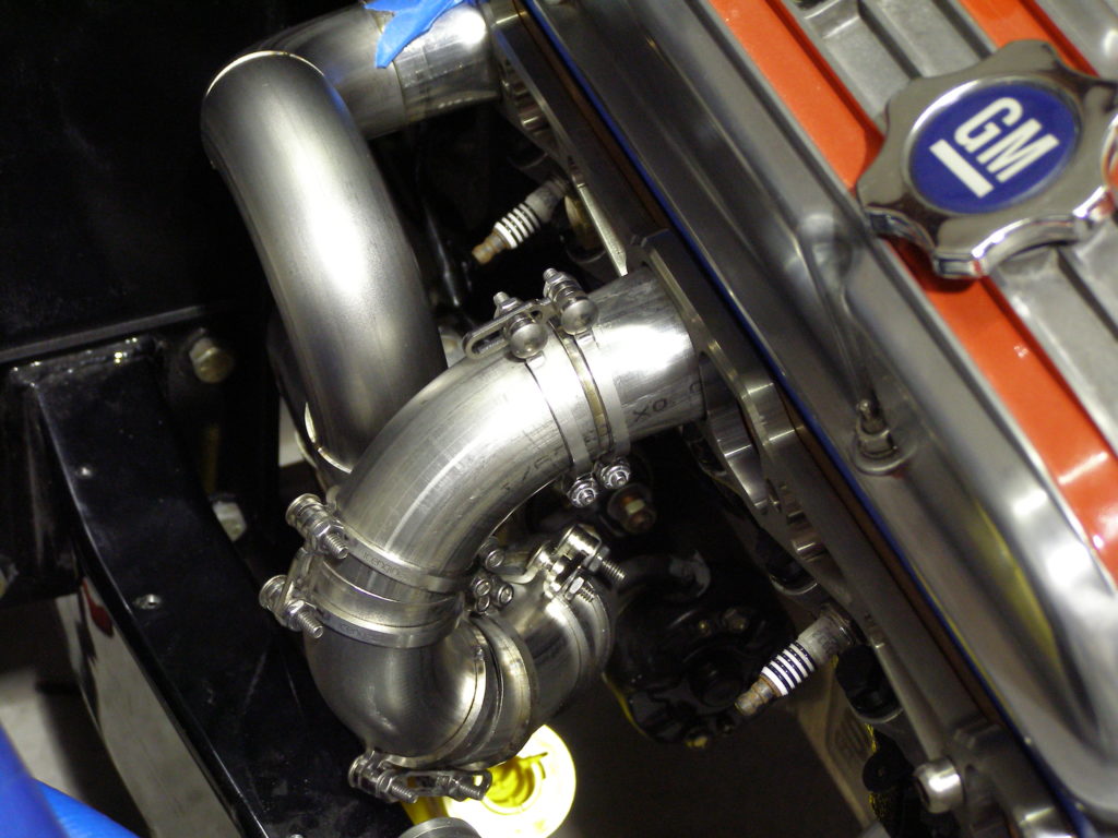
Assembly and welding
After the individual metal sections for the project are cut, builders move to STAGE III: Assembly and Welding. STAGE III utilizes one of the most innovative products to hit the fabrication industry in decades: the patented icengineworks™ stainless steel tack-welding clamps.
These clamps provide an amazingly quick and exact way to hold multi-sectional tubular assemblies together. Proper relative rotation at each joint is easily and minutely adjusted until the entire assembly becomes a solid recreation of the original plastic block model. They provide endless opportunities to verify fitment for clearance, accuracy, and exact alignment with the receiving tube ends at the head flange, exhaust collector or Collector Dummy prior to tack-welding the assembly. Sold in sets of 4.